
Thursday, 12 September 2019
Quick Profile
Just found out today that the Quick Profile command is available from the default right-click menu when an object is selected! I don't know which version that started to be in there (maybe the first version!?) but really handy to have.


Thursday, 5 May 2016
NCOPY and Civil 3D corridors
Quick post to remind myself.
If NCOPY is used to a corridor, Civil 3D creates a new copy of it.
If NCOPY is used to a corridor, Civil 3D creates a new copy of it.
Thursday, 3 March 2016
Civil 3D 2015 Surface to Navisworks 2015 Problem
I was recently appending a Civil 3D surface (2015) into Navisworks Manage 2015. For some reason, I only get a rectangle in Navisworks. It however appends into Navisworks Manage 2013 fine.
Thanks to this blog, found out that I needed to install the Civil 3D 2015 object enabler. The link on the blog seems to be broken so here's the link to the Civil 3D 2015 OE.
AutoCAD Civil 3D 2015 Object Enabler
Thanks to this blog, found out that I needed to install the Civil 3D 2015 object enabler. The link on the blog seems to be broken so here's the link to the Civil 3D 2015 OE.
AutoCAD Civil 3D 2015 Object Enabler
Friday, 12 February 2016
Isopachyte and Surface Analysis Tools
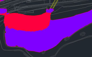
An isopachyte shows level differences between 2 surfaces using different colours to represent level ranges. They're mostly used on earthworks projects to indicate the areas of cut and fill. The example figure below shows areas in cut as red and fill in purple.
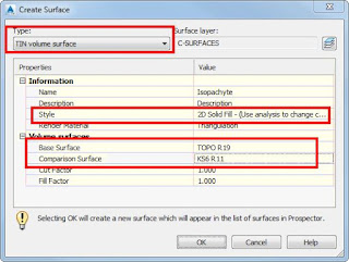
To produce an isopachyte, create a TIN volume surface and choose the base and comparison surfaces.
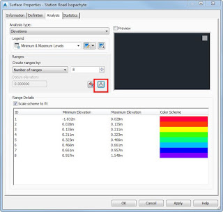
Under the Analysis Tab of the surface properties, set the number of ranges needed and click the Run Analysis button.
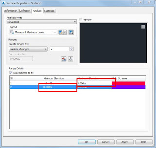
Ranges can be changed to suit. Say if cut and fill areas are only needed, set the range to 2 and change the maximum and minimum levels to 0 for ID1 and ID2 respectively.
A table can be added as a key to the level ranges of each colour.
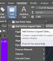
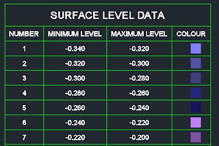
There are tools included within the UK and Ireland Country Kit that help copying surface analysis from one surface to another without redoing the changes made to the range table.
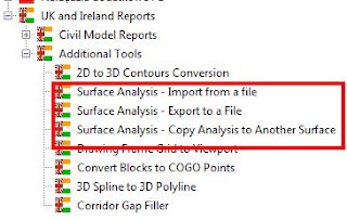
Surface Analysis - Import from a file / Export to a File
These can be used if copying a surface analysis from a drawing to another.
Surface Analysis - Copy Analysis to Another Surface
This can be used if the surfaces are in the same drawing.
Have a good weekend!

To produce an isopachyte, create a TIN volume surface and choose the base and comparison surfaces.

Under the Analysis Tab of the surface properties, set the number of ranges needed and click the Run Analysis button.

Ranges can be changed to suit. Say if cut and fill areas are only needed, set the range to 2 and change the maximum and minimum levels to 0 for ID1 and ID2 respectively.

A table can be added as a key to the level ranges of each colour.


There are tools included within the UK and Ireland Country Kit that help copying surface analysis from one surface to another without redoing the changes made to the range table.

Surface Analysis - Import from a file / Export to a File
These can be used if copying a surface analysis from a drawing to another.
Surface Analysis - Copy Analysis to Another Surface
This can be used if the surfaces are in the same drawing.
Have a good weekend!
Tuesday, 15 December 2015
GENIO Import/Export Extension for Civil 3D
The ability to export corridor and alignment objects from Civil 3D to MX using the GENIO export extension has been useful for me the past few months whilst working on a highways scheme that uses MX as the main design package. I designed 2 local roads using Civil 3D and exported the corridor featurelines so we can add to the main MX model. The featurelines were named correctly in Civil 3D to be recognised in MX (ie. CExx for edge of carriageway, IAxx for daylight, CBxx for back of kerb, etc where xx is a 2-digit number).
One thing to remember is that the exporter doesn't give the ability to choose which design profile to export but will export all designed profile for the chosen alignment.

The tool uses the profile that was created first and ignores the rest.

One thing to remember is that the exporter doesn't give the ability to choose which design profile to export but will export all designed profile for the chosen alignment.
The tool uses the profile that was created first and ignores the rest.
The GENIO screenshot below shows my superseded profile within the red box and current design profile in blue box. For info, MX ignores any coding lines that has 3 spaces before of it.
Something to be mindful of when using the tool and always check the GENIO output before using.
Monday, 21 September 2015
Resizing Model Space Viewport
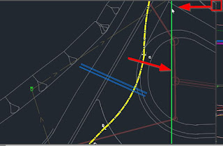
Just only noticed this today. On Civil 3D 2015, model space viewports can now be easily resized by dragging the border between viewports.

Another button with a plus (+) symbol allows you to add a new viewport. To add a new viewport, click on the plus button and drag. When adding a viewport, the dragged border colour turns to green. Nice!

Another button with a plus (+) symbol allows you to add a new viewport. To add a new viewport, click on the plus button and drag. When adding a viewport, the dragged border colour turns to green. Nice!

Wednesday, 2 November 2011
Old Stuff
Was doing some tidying up yesterday and found these. LDD 2i and Civil Design 2 User's Guides. I'm now hunting for the Softdesk 8 guides.
The good old days! :-)
Blogger for Android

Wednesday, 26 October 2011
Alignment Widening
To add a widening to an offset alignment, we can do it through ADDWIDENING command in the command line, Ribbon, Right-click and Toolspace or using Grips.
I was modelling the alignment of a central reserve concrete step barrier for a motorway refurbishment scheme recently and found out the difference between the two.
When using the ADDWIDENING command, the offset width before and after the widening are exactly the same.

And if I grip edit and try to change the offset width, both offsets move simultaneously.

And if I grip edit and try to change the offset width, both offsets move simultaneously.

With grips however, the offsets' width can differ and be independent from each other.

Below is a screenshot where I try to change the offset width to the left of the widening while the width on the right stays.

Essentially, Civil 3D creates 2 widening groups when using Grips.
The first with all widening elements; transition in & out and a widened region.

While the second group only has a transition in (which is also the transition out of the first widening group) and the widening.

Monday, 24 October 2011
Section View – Offset Labels For 2 Surfaces On One Section Band
We have two separate surfaces shown on a section view and we’d like to show offset labels for both surfaces in one band box. Both surfaces came from two different types of surveys so we’d like to show them separate on section view (i.e. different linetype and colour).

I could think of two ways to do this. One is by combining the 2 surfaces. Second is by manipulating data bands.
Option 1
This is the quicker and simpler of the 2. Combine the 2 surfaces and sample the new combined surface.


Hide the section line from View.

Use the combined surface data for the bands.

Option 2
This option is a little messy but just thought it would be good to include this anyway to show an example on how labels can be manipulated to get desired presentation.
Copy the current Offset band style.
This option is a little messy but just thought it would be good to include this anyway to show an example on how labels can be manipulated to get desired presentation.
Copy the current Offset band style.

Under Band Details tab, select the type of label you want to show, for my example I’m showing labels at section Gradient Breaks and select Compose label… Take note of the Band Height used.

Change the Y-Offset to whatever band height you have above, 15 for my example. Basically, what I’m doing is creating a new Offset band box and moving all labels (and ticks if any) one box up but showing only the labels.


Back to the Display Tab in Data Box Style, turn off all components except for Ticks and Labels at Gradient Breaks.

Add the new band style to the set and change the surface for Section 1. Thus on my example below, the style ANZ_(Rd) - Offsets (Grade Breaks) refers to the Hydrographic Survey surface (red section lines) and ANZ_(Rd) - Offsets (Grade Breaks) 2 refers to the Ex_Contours_Adjusted surface (green dashed line).


Thursday, 30 June 2011
Tuesday, 17 May 2011
Civil 3D 2012 - Hide Assembly
A new Assembly command in Civil 3D 2012 is REMOVEASSEMBLYFROMMODELSPACE. As what the command says, it removes / hides the assembly from modelspace. Useful if you are working on a lot of assemblies and just want to see the one you're working on currently. I like my drawing tidy so I quite like this.

To insert the assembly again for editing, simply go to Toolspace, find and right-click the assembly and select Insert to Modelspace.

Minor new feature but very handy.
I'll post more once I see one.

To insert the assembly again for editing, simply go to Toolspace, find and right-click the assembly and select Insert to Modelspace.

Minor new feature but very handy.
I'll post more once I see one.
Friday, 8 April 2011
Swap / Change Subassemblies
Quick one before I leave work for the day.
Just found this feature this afternoon and using Civil 3D 2010 at that!

Just found this feature this afternoon and using Civil 3D 2010 at that!
To quickly change / swap a subassembly with another, go to Subassemblies Tool Pallettes, right click the subassembly you want to use, click Apply Tool Properties to Subassembly and click the one you want replaced. Sweet!
Have a good weekend everyone!

Friday, 18 February 2011
Reminiscing
Look what I found in my drawer! It's the installation disc for Civil 3D 2004 Preview release.
Coming from an LDD and Civil Design background and first time user of an object-based design software, I was amazed on how easy it was to use and how each design object is linked to one another thus making changes a quicker process. This made me realise its potential and how this tool can greatly help me at work.
I was so excited about the product that I left work late that day playing and exploring it. Even used it on a live project even though I shouldn’t!
Good weekend everyone!

Tuesday, 1 February 2011
Point Labels
I am currently preparing site clearance appendices and drawings for a motorway refurbishment scheme to form part of the works information document.
To produce the drawings, I need to label 700+ existing road lighting columns to be taken down. I also need to tabulate these items onto a Word document so Civil 3d Points fit the job. I want to have a label showing the site clearance item reference inside a circle with an arrow pointing to the item similar to below.

The label style is composed of 4 components that include 2 blocks, 1 text and a line.

So I start by creating a block component using a block consisting of a hatched circle. Component properties as image below.

The text component to show the item reference. These are Point Numbers with “CC” prefix added to them. I used the block component above as an anchor. Component properties as below.


Next the Line component which I again anchored to the block component with properties as below.

Finally another block component using an arrow block this time using the line component as an anchor.

The anchor component is important so that each component remains linked if the label is dragged / moved. To drag the label, simply activate the sub item grips. Select the label and click the blue round grip. Grips will then appear for each component.


Since all other components are anchored to each other, if I grip move the circle, everything else follows.

To reset to the labels default location, click and right click the label and Reset Label.

Monday, 31 January 2011
Corridor Modelling (Practice)
Due to limited number of projects at work, I haven’t been using Civil 3D to do design work lately. Use of software and its features can be easily forgotten if not used for a long period of time so to refresh and practice myself, I do corridor modelling during my free time.
I picked Junction 33 of the M4 motorway to “model”. I brought in Google images as guide to trace my horizontal alignments over and Google surface for my existing ground. I used Civil 3D 2011, the new corridor tools just made corridor modelling a lot easier. It is a work in progress and I intend to import it into 3DS Max with Dynamite once done. Plenty more to do but should keep me busy during lunchtimes!


Friday, 1 October 2010
Civil 3D 2011 Subscription Advantage Pack
This week saw the launch of Subscription Advantage Packs for 2011 Autocad products including Civil 3D.
Only a handful new features compared to last year's but equally useful. Though I was more excited to hear the release of Update 1 to be honest.
Particularly like enhancements made to importing points and the new(ish) Import Styles and Settings command. I said newish because this was an undocumented command on Civil 3D 2011 pre-SAP. The SAP version now has a dialogue window when the command is executed.
More details and videos here or click the image below.

Only a handful new features compared to last year's but equally useful. Though I was more excited to hear the release of Update 1 to be honest.
Particularly like enhancements made to importing points and the new(ish) Import Styles and Settings command. I said newish because this was an undocumented command on Civil 3D 2011 pre-SAP. The SAP version now has a dialogue window when the command is executed.
More details and videos here or click the image below.
Wednesday, 29 September 2010
Autocad Civil 3D 2011 Update 1
Update 1 has been released. This certainly solved an issue we're having - opening drawings with featurelines projected onto multiple sections. What used to be a wait of more than 10mins is now down to 1min.

Although I haven't checked, it should also resolve the issue we are having with plotting dwgs to pdfs.

Update 1 and README can be downloaded here.

Although I haven't checked, it should also resolve the issue we are having with plotting dwgs to pdfs.

Update 1 and README can be downloaded here.
Subscribe to:
Posts (Atom)

 Posts
Posts


