Wednesday, 3 February 2010

Profile from file

A recent post from the company's internal discussion forum was raised on how to create a breakwater long section (complete with band levels and chainages) without any ground data and only a spreadsheet data on hand similar to below.


I'm sure skilled programmers can easily produce an Excel VBA script or similar and output into a dxf file. Another option is to do it manually but will surely take ages. Here's how to do it in Civil 3D.

Create a new drawing. Create an alignment with length equal to the last chainage on the spreadsheet. This can simply be a long straight alignment. Create a profile view.

Next remove any headers on the spreadsheet leaving only the values. Save the spreadsheet to a .prn file (space delimited) format. Then change the file extension to .txt as this is the format Civil 3D will look for.


Import the text file. Profiles> Create Profile from File.


Once the profile line appears on profile view, the profile source might need to be set for correct values in the bands.

Wednesday, 27 January 2010

Section View Axis Offset

We lately had some confusion at work when one of our technicians was given an exported Civil 3d section to work up details and setting out drawings for a motorway variable message sign foundation.

He was offsetting the section view left and right axes to set out the foundation which he assumed correspond with the ends of the section line.  The offset lines however appear to be in the wrong place when checked against the carriageway features on plan.

Going back to the Civil 3D drawing where the section was exported from, we found out that the problem was the left and right axes offset of the section view style being set to 5.  This made the cross section view 10 units longer than the section line – an extra 5 on each end.  Setting it to 0 corrected the problem. 

02-_Screenshot

01-_Axis_offset 

Also worth noting that the axis offset values are specified in plotted units based on the drawing scale set on the Drawing Settings (Toolspace, Settings tab> right click the drawing name> Edit drawings settings).  I.e. if the drawing setting scale is set to 1:500 and the axis offset is set to 5, the offset on the drawing will be 2.5.

03-_Drawing_settings

Tuesday, 29 September 2009

Customising alignment label styles

We just sent our deliverables for the outline design stage of a road renewal scheme I was working on the past few months out the door last Friday. This week should be a quieter one that I can probably squeeze in a post or two during lunchtimes before the next stage kicks off next week!

Before I start on the main topic, a quick note that Civil 3D 2010 Update 2 have been released and can be downloaded here.  As usual, it is recommended to read the Readme file prior to installing.

OK, here’s another post on customising alignment labels styles. This is my stab at creating an alignment style similar to the image below.
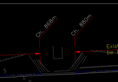
Label

Alignment labels can be created/edited through the Settings tab in Toolspace or through the Add labels dialog box; Alignment>Add alignment labels. I often do the latter.

Labels-fixed_point

Create a new label style and name it Chainage (or Station).

Labels-new

On the General tab, change the Orientation reference to Object.  This will ensure that the extension line of the label will always be perpendicular to the alignment.

Labels-view

I will be creating 3 components. 1 line for the extension from the label point, another line for the landing and a text for the chainage number.

Click on the Layout tab and delete any existing component.

First create a new text component.

Labels-text_new

Add the Chainage value field to the text contents and use the parameters as below.
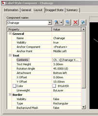
Labels-text1

Then create the line for the extension from the label point with parameters as below.  I have Line.1 as component name (this is the default that Civil 3D creates) but this can be changed to a more sensible name anytime.

Labels-line1_newLabels-line1_props

Next is to create the landing (the line below the text) with parameters as below.

Labels-line2_props

To create a label below the alignment, copy the style previously created. On the Layout tab, change the rotation angle to 315 and Y-offset to -10 of the chainage text component.

Labels-bottom_props

Here’s how the labels look like above the alignment.
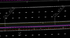
Label-final1

And here it is below the alignment.

Label-final2

Hope this helps or at least gives ideas on how to create and customise alignment label styles.

Saturday, 22 August 2009

Autodesk Civil Engineering Curriculum 2010 Videos

Just noticed a series of educational videos from the Autodesk channel on Youtube.   There are a total of 29 videos grouped into units and a number of lessons in each unit.

“These videos support the Autodesk Civil Engineering curriculum and help to demonstrate engineering concepts using the Autodesk portfolio. To view the entire curriculum, including Instructor Guides and Student Workbooks, visit the Autodesk Student Community. www.autodesk.com/edcommunity”

I posted below the links to each lesson.  Enjoy!

Unit 1: Autocad Civil 3D 2010 Environment

Lesson 1: Drawing environment

Lesson 2: Civil 3D user interface

Lesson 3: Settings and Styles

Unit 2: Create Ground Data

Lesson 1: Create Survey Data

Lesson 2: Create Points

Lesson 3: Surfaces

Lesson 4: Insert Images

Unit 3: Land Development

Lesson 1: Grading

Lesson 2: Create Parcels

Lesson 3: Horizontal Alignments

Lesson 4: Profiles

Lesson 5: Assemblies and Corridors

Lesson 6: Cross Sections and Quantities

Lesson 7: Site Grading and Quantities

Lesson 8: Pipe Design

Unit 4: Environmental Design

Lesson 1: Sustainable Design

Lesson 2: Watershed Analysis

Lesson 3: Pipe Design

Lesson 4: Integrating Architectural and Site Design

Unit 5: Transportation Design

Lesson 1: Alignments

Lesson 2: Profiles

Lesson 3: Roadway Assemblies and Corridors

Lesson 4: Cross Sections and Quantities

Lesson 5: Plan Production

Unit 6: Geospatial

Lesson 1: Using Geospatial Data

Lesson 2: Geodetics

Lesson 3: Queries

Lesson 4: Cartography

Lesson 5: Spatial Analysis

Monday, 3 August 2009

Civil 3D 2010 Update 1 now available

Update can be downloaded here.  Remember to read the Readme file for installation instructions and to see what issues were resolved by this update.