Monday, 21 September 2015

Resizing Model Space Viewport

Just only noticed this today.  On Civil 3D 2015, model space viewports can now be easily resized by dragging the border between viewports.


Another button with a plus (+) symbol allows you to add a new viewport. To add a new viewport, click on the plus button and drag. When adding a viewport, the dragged border colour turns to green. Nice!


Wednesday, 2 November 2011

Old Stuff

Was doing some tidying up yesterday and found these. LDD 2i and Civil Design 2 User's Guides.  I'm now hunting for the Softdesk 8 guides. 

The good old days! :-)

Blogger for Android


Wednesday, 26 October 2011

Alignment Widening

To add a widening to an offset alignment, we can do it through ADDWIDENING command in the command line, Ribbon, Right-click and Toolspace or using Grips.

I was modelling the alignment of a central reserve concrete step barrier for a motorway refurbishment scheme recently and found out the difference between the two.

When using the ADDWIDENING command, the offset width before and after the widening are exactly the same.


And if I grip edit and try to change the offset width, both offsets move simultaneously.


With grips however, the offsets' width can differ and be independent from each other.


Below is a screenshot where I try to change the offset width to the left of the widening while the width on the right stays.


Essentially, Civil 3D creates 2 widening groups when using Grips.
The first with all widening elements; transition in & out and a widened region.


While the second group only has a transition in (which is also the transition out of the first widening group) and the widening.

Monday, 24 October 2011

Section View – Offset Labels For 2 Surfaces On One Section Band

We have two separate surfaces shown on a section view and we’d like to show offset labels for both surfaces in one band box.  Both surfaces came from two different types of surveys so we’d like to show them separate on section view (i.e. different linetype and colour). 


I could think of two ways to do this.  One is by combining the 2 surfaces.  Second is by manipulating data bands.

Option 1
This is the quicker and simpler of the 2. Combine the 2 surfaces and sample the new combined surface.


Hide the section line from View.


Use the combined surface data for the bands.


Option 2

This option is a little messy but just thought it would be good to include this anyway to show an example on how labels can be manipulated to get desired presentation.

Copy the current Offset band style.


Under Band Details tab, select the type of label you want to show, for my example I’m showing labels at section Gradient Breaks and select Compose label…  Take note of the Band Height used.


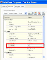
Change the Y-Offset to whatever band height you have above, 15 for my example.  Basically, what I’m doing is creating a new Offset band box and moving all labels (and ticks if any) one box up but showing only the labels.


Back to the Display Tab in Data Box Style, turn off all components except for Ticks and Labels at Gradient Breaks.


Add the new band style to the set and change the surface for Section 1.  Thus on my example below, the style ANZ_(Rd) - Offsets (Grade Breaks) refers to the Hydrographic Survey surface (red section lines) and ANZ_(Rd) - Offsets (Grade Breaks) 2 refers to the Ex_Contours_Adjusted surface (green dashed line).