I'm sure skilled programmers can easily produce an Excel VBA script or similar and output into a dxf file. Another option is to do it manually but will surely take ages. Here's how to do it in Civil 3D.
Create a new drawing. Create an alignment with length equal to the last chainage on the spreadsheet. This can simply be a long straight alignment. Create a profile view.
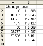
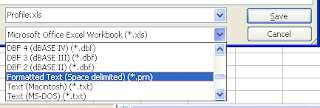
Next remove any headers on the spreadsheet leaving only the values. Save the spreadsheet to a .prn file (space delimited) format. Then change the file extension to .txt as this is the format Civil 3D will look for.

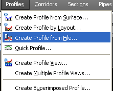
Import the text file. Profiles> Create Profile from File.

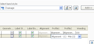
Once the profile line appears on profile view, the profile source might need to be set for correct values in the bands.


