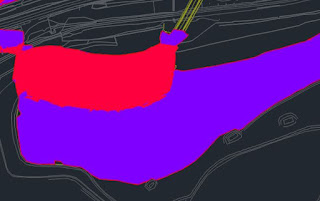
An isopachyte shows level differences between 2 surfaces using different colours to represent level ranges. They're mostly used on earthworks projects to indicate the areas of cut and fill. The example figure below shows areas in cut as red and fill in purple.
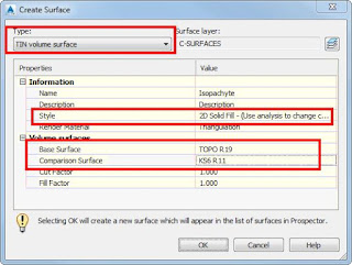
To produce an isopachyte, create a TIN volume surface and choose the base and comparison surfaces.
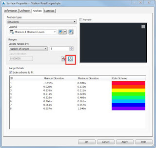
Under the Analysis Tab of the surface properties, set the number of ranges needed and click the Run Analysis button.
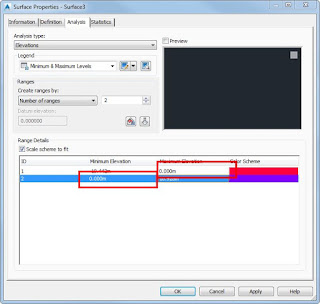
Ranges can be changed to suit. Say if cut and fill areas are only needed, set the range to 2 and change the maximum and minimum levels to 0 for ID1 and ID2 respectively.
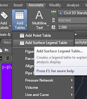
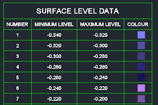
A table can be added as a key to the level ranges of each colour.
There are tools included within the
UK and Ireland Country Kit that help copying surface analysis from one surface to another without redoing the changes made to the range table.
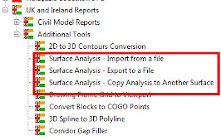 Surface Analysis - Import from a file / Export to a File
These can be used if copying a surface analysis from a drawing to another.
Surface Analysis - Copy Analysis to Another Surface
This can be used if the surfaces are in the same drawing.
Have a good weekend!


