Showing posts with label Corridors. Show all posts

Monday, 31 January 2011

Corridor Modelling (Practice)

Due to limited number of projects at work, I haven’t been using Civil 3D to do design work lately.  Use of software and its features can be easily forgotten if not used for a long period of time so to refresh and practice myself, I do corridor modelling during my free time.

I picked Junction 33 of the M4 motorway to “model”. I brought in Google images as guide to trace my horizontal alignments over and Google surface for my existing ground. I used Civil 3D 2011, the new corridor tools just made corridor modelling a lot easier. It is a work in progress and I intend to import it into 3DS Max with Dynamite once done. Plenty more to do but should keep me busy during lunchtimes!

M4J33Plan

M4J33

Monday, 9 February 2009

90 degree road bend

There recently was a topic in the Civil 3D discussion forum on how to model a corridor that have a 90 degree bend alignment (no curve at all). The problem when modelling this is the inside lane of the corridor will have overlapping corridor links. This post will discuss a workaround on how to achieve this. Please note I am using Civil 3D 2009. This still can be done in earlier versions but would take longer though.

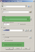
Assuming horizontal alignment and vertical profile already exist, create a feature line from alignment, use the designed profile and untick "Create dynamic link to alignment box". Click OK and accept the defaults in the Weed Vertices dialog box.

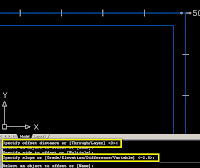
Create a stepped offset from the centreline featureline to desired road cross fall slope for both sides. In this case I used -2.5% slopes and 3m offsets.


Add a free curve with radius value of the half lane width which is 3m and create the road assembly.
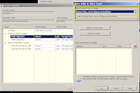
Create a corridor with tangent frequency set to 5 and curves set to 2. Set the offset featurelines as horizontal and vertical targets. This feature is new in 2009 and makes the task easier to do.
Add an extra chainage to define the outer corner.
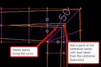
The corridor surface needs a few editing to run the crown along the centreline corner and not along the centreline curve. Create a surface from the corridor and set the style to show the surface points. Delete the points along the curve and add a point at the centreline corner with levels taken from the converted centreline featureline.
Finally, to add the earthworks, create grading using the road edge featurelines and use the existing ground surface as target. Add the new grading to the corridor surface by right clicking on the grading featureline and “Add surface as breakline…”. Select the corridor surface in the next dialog box and accept the defaults in the “Add breaklines” box.